700r4 "The Nemesis" Rebuild - Part 1
Download information and video details for 700r4 "The Nemesis" Rebuild - Part 1
Uploader:
Nick's TransmissionsPublished at:
4/7/2025Views:
1.5KDescription:
Video Transcription
Hey there and welcome.
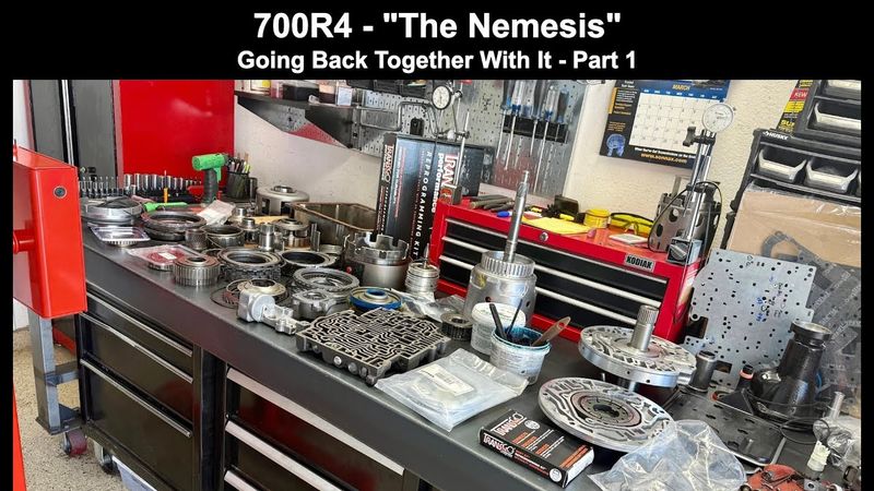
Today we're going to be putting the Nemeziz back together.
So we have already installed the Transgo 2 and 3 kit into all the components to take all the parts from that kit.
That was quite an extensive install and an even longer video.
It's over three hours long.
So if you're curious, check it out.
i have it segmented into chapters and it's more or less meant to be consumed in parts and pieces you know specific aspects of the kit that you're curious about uh that you want to learn how to do uh you know that's how it's meant to be consumed i mean sure you could watch it all three hours of it in one sitting if you're brave enough if you have the
endurance, but I didn't really intend it for that.
But anyway, this video is going to basically serve as a record for how this transmission went together, and it'll probably be a two-parter where I will do all the sub-assemblies in this one, this video you're watching now, and then part two will consist of everything into the case and final assembly.
So I'll
I'll touch on some of the things that we did for the shift kit so that you have that context in the event you're watching this one first.
And just to give you a little background and a little history as to why I'm referring to this as the Nemesis.
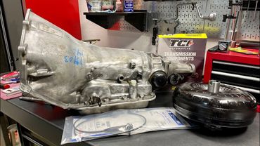
This transmission was brought to me by a customer down in Phoenix.
I'm in Vegas and he drove it all this way.
And I really appreciate that.
Unfortunately, this is not the first time this transmission is being rebuilt, at least not in the last six months.
He originally purchased it from a fairly large transmission remanufacturing company, and this company dubbed it the Nemesis, and they were advertising this thing to handle 500 plus horsepower.
unfortunately that is very far from the truth when we tore it down and inspected it we saw that other than a basic sunshell half inch boost valve blocking the fourth accumulator and maybe one or two other things they did not do much in the way of setting this transmission up for success especially not in a high performance high rpm you know type application as advertised so
We're basically going to correct all the things I didn't do or did wrong and put this thing back together so that it can thrive and survive in the application, which of course, I guess I shouldn't say of course, because I'm assuming this is the first of this video mini series you're watching.
The application is a 1988 Chevy C10 GMT 400 platform two-wheel drive truck.
And it has a small block, 383, making about 450 horsepower or so.
Anyways, we're going to walk you through the process from start to finish.
One of the things that we need to do is install the drum reinforcement kit into the forward drum.
That's a Sonix product.
And then build up both of the drums, get everything set and installed into the case so that we can dial in our end play.
And that's front end play, input shaft and pump.
And then from there, we'll go ahead and perform a holistic case air check.
We also have to install the servo assembly and get band clearance dialed in as well.
So a lot to do.
So let's get cracking.
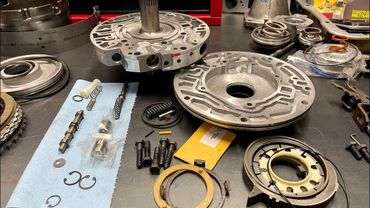
Alright, we're going to begin with the pump.
Now before you start putting anything into the pump body, the first thing you want to do is check your clearance between your rotor and deck surface as well as your slide and deck surface.
So this is the slide and this is the rotor.
This is the bottom side of the rotor where you have your engagement lugs for your rotor guide.
That's this plastic piece right here.
And then this is going to be the top side.
So this is a brand new rotor and slide in a freshly machined pump body.
So just take a straight edge, stick it across.
And then I have two feeler gauges here.
I have a one thou feeler gauge and a one and a half thou feeler gauge.
Clearance you need to manage to between the deck surface of the pump body and the top of the slide is between one and two thousandths.
The deck surface to the rotor is between one and one and a half thousandths.
So even before you use your feeler gauges, what you may want to do is just simply rotate the rotor all around
to make sure it's not coming in contact with your straight edge and do the same with the slide okay the slide's obviously not going to rotate 360 degrees but you can rotate it as far as it'll travel within the pocket to determine if it's going to make contact with the straight edge which is obviously indicative of an interference fit which is the last thing you need so let's try one and a half thou and see how that fits
Okay, that's sliding under.
It's scraping both surfaces, but it is sliding underneath the slide.
So it's one side.
There's the other.
It is beginning to move the slide on this side.
So now we'll try the one thou gauge.
Okay, that's fine.
And that's fine.
Rotor.
Okay, we have space.
And we have space.
Okay, this is scraping both sides.
As is this.
So I'm comfortable with what I see here.
I basically have one and a half thou clearance between the slide as well as the rotor and the deck surface respectively.
So we can go ahead and proceed with the assembly of this pump.
Now all, you know, spirit of full disclosure, I already did this measurement process.
In fact, I measured at multiple different points just to make sure that everything is consistent.
And that's what I would recommend that you do.
So you may have noticed I installed the seal.
Don't install the seal until you know that the rotor and slide is good to go in relation to the deck surface.
All right.
Admittedly, I'm not going to show some things.
There's like small tasks that I completed off camera just primarily in the interest of time because I am somewhat under the gun with this thing.
Customer would like to pick it up this Saturday.
Today is Thursday.
And as you can see, we have a fair amount of work ahead of us.
So this is the Transgo Unbreakable Pump Ring Kit.
So this kit is designed to be fitted to transmissions where the engines are going to be revving over 5500 RPMs.
I mean, you do what you want, but my advice is to only buy this kit.
Transgo makes another kit that's designed for engines that will rev up to 5500, I guess, but not over.
it really doesn't make a difference insofar as this kit being good to go for any RPM regime.
So that's why I always order this kit as opposed to the other one.
All right, let me move this camera just a little bit and then we'll go ahead and put the pump body together.
The stator has already been assembled.
The only thing we really need to do with that thing is to install the Teflon sealing rings and the whole pump assembly will be done.
Always lube up your bushing, your seal, and your working surfaces before installing any parts.
So, as I mentioned, this pump kit itself is brand new.
I gotta go find the...
I gotta go find the slide support.
I inadvertently put it in the drawer for some stupid godforsaken reason.
Alright, so FYI, there are 7, 10, and 13 vane pumps for these transmissions and 204Rs, 4L60Es.
For the 700s, you can interchange 13 vane setups, you know, retro them back to 10 vane pumps.
I don't know that the gains are going to be all that worth it.
I know a lot of guys like to do it, but...
10-vane pumps are usually sufficient.
And I'll be perfectly honest with you, and this may sound a little heretical, but even 7-vane pumps are fine for any conceivable application.
The nice thing about the 7-vane pumps is that they're the strongest in terms of the rotor because you have less slots.
And for 204Rs, you really don't need a 10-vane pump at all.
The 7-vane variety is more than sufficient.
So here's how I install my slides.
I just take the slide in one hand and the body in the other, and I'll just go right over top and kind of make them that way.
This way, your slide support, you don't have to worry about it falling out.
All right, brand new things.
always install new veins.
All right.
So the first things you want to put in in terms of little parts are going to be your little Teflon spring and spring seat or a spring support.
They go like that.
And then your pivot pin and corresponding spring.
You may have to kind of help it get in there by squeezing the slide against the wall here.
And then just push it in.
Alright, for the slide spring or priming spring itself, the preferred tactic, at least for me, is to take a big old screwdriver.
I will position
you know, the casting against my belly.
And then I will just simply lever the spring, wedging it into the pocket.
So against the belly.
And then push while you lever the screwdriver toward you.
And that will get it up in there fairly easily.
All right, now your rotor and rotor guide.
Now, I would never recommend you do this, ever, but if you're going to reuse pump vanes, you want to make sure you install them in the same orientation, meaning you want the side here, the long axis facing the slide, going back with it,
as it was when you pulled it out.
And the easiest way to tell is that anything that's going to be facing the slide, any part of the vane that is facing the slide is going to be shiny and have a wear pattern from the top to the bottom.
Any side that faced the rotor will have shiny spots here and here, or witness marks up on one side and the other.
Okay, the rest of it will be, you know, largely unaltered in terms of appearance.
So that's the best way to determine, you know, which way the, you know, vein needs to go.
But these vein kits are like $5 to $10, you know, pretty much everywhere, no matter where you might source them.
And it makes no sense to reuse the veins.
And I've seen a lot of builders do it too on YouTube.
I mean I used to watch transmission building videos all the time before I started my own channel.
And you know guys would reuse the vanes.
And you know they would install them just as I described.
It's not the end of the world, but for me, I just prefer to put new.
This is a wearable or a consumable.
So, you know, just like clutches and bands and, you know, steels to a large extent, electrical components, you know, it's a wear item, so you should replace it.
That's my opinion, of course, but that's how I like to do it.
All right, you're going to need an alignment tool.
I get a lot of questions about this thing.
A lot of folks want to know where I got it and what I paid and all that.
Unfortunately, I bought this off eBay 10 years ago.
I say unfortunately because I was actually looking for one of these recently.
I wanted to get a backup and I could not find another one like it.
And the seller, I'm assuming...
is no longer active on ebay you know this looks like somebody you know was making these you know a small business perhaps was making these and you know they'd stop making them which sucks all right
So for your mating of the body and the stator, what I like to do is I'll look for these two holes here and I'll look for the corresponding two holes on the stator, stator support.
And that's how I will attack it.
Make sure you put lube over here.
I have bushings installed.
I will make a comment here about...
Sonics bushings, and I've been noticing this lately.
I'm just going to say it.
I'll have to reach out to Sonics, so admittedly, I haven't done so.
But it seems like, I don't know if there's something going on with their bushings, the way they're producing them, or, you know, some things are out of spec.
But the rear stator bushing and the bushing that goes into the rear sun gear, their wide rear sun gear bushing, for the last several transmissions I have built, those bushings would not fit their respective journals.
And because you have Teflon coating on this bushing here, you know, the Sonix counterpart bushing, you can't really sand that down, and you're not going to sand the journal down sufficiently enough, you know, on the input shaft to make them both fit.
I mean, it was severely tight.
Hey, this is just a basic bushing, you know, the wider version.
Two versions of this bushing will come in the kit.
You always want to use the wide one, but...
You know, the bushings from Sonics were not fitting.
Alright, if you watched my recap video, you have recalled that there was different styles of pump head bolts used.
Now I want to see, maybe I already switched these out.
Maybe I did.
No, I didn't.
So you'll notice this bolt here and this bolt here have shorter threadless sections than these three.
And I'm not going to lie to you, I just pulled random bolts out of the drawer.
I have all my bolts organized and I just happen to have some that are long and this one is short.
I don't know which is correct.
If you guys know, you know, anybody that builds these, you know, all the time, all day, every day, let me know.
But I'm just going to put all five in that are identical.
Interesting tidbit.
All right, get your bolts threaded in, you know, get them started and then go ahead and set up your alignment tool.
These pumps have to be perfectly aligned.
Otherwise they will not want to go in.
And a lot of times they will be stubborn anyway, regardless, but you know, if you want any chance at all for a smooth installation, when it comes time to put the pump back into the case, you need to make sure that it is perfect.
take this one out.
I think I need to push one of these two halves in a particular direction.
Alright, the band looks reasonably level.
I'm actually centered on my bolt holes, so I'm not sure.
This one is tight for some reason.
Maybe I was about to cross thread it.
I don't know.
Alright, torque spec is 15 foot pounds.
I'm going to get it off the little stand here.
And then just go every other bolt.
I like to start with these two bolts, one of these two right here.
And it looks like it's getting caught on the feed pipe.
Cramping my style.
Every other bolt.
So in a more or less crisscross pattern, as if you were tightening lug nuts on a five axle wheel.
Five bolt axle wheel.
Excuse me, yeah, five axle wheel.
Five axle wheels, man.
You guys have any five axle wheels in stock?
One of mine broke.
That stupid pipe.
Alright.
Leave the alignment tool on there.
I got the servo in my way.
I like to have a checking tool on the bench with an easy reach so that I can confirm or deny that everything is good inside this pump.
Okay, go around maybe two or three times.
Okay, two or three times, that'll give you the assurance you need to know that it's good to go.
I have a variety of checking tools for all different transmissions in there, as you've heard.
Or just heard, I should say.
Alright, pump O-ring.
What I've been doing is I haven't been checking end play by leaving the O-ring off.
I've just been installing it.
And my reasoning is that it's not really any more time consuming or tedious to get the pump out with the O-ring, with all the assembly leave and whatnot on there as it is.
Not.
In other words, dropping it in dry.
In fact, in some cases, depending on
you know the individual transmission you're working on and maybe even more difficult to do it using the latter method so lately I just been I just been installing it as if it's going in for the final time and if I have to take it out no big deal what I'm looking for is the two tab washer and I tossed the one that came on here originally because it was it looked like it was about to crack and break apart
So if your washer looks like this, it's perfectly fine.
The washer that came in on this transmission looked like it was burnt.
And it looked like it was burnt during a prior incarnation of that transmission's life.
In other words, before that reman company got to it.
I mean, they used as much as they possibly could to cut as many corners from a cost perspective as possible.
And, you know, unfortunately that's what you have to deal with in the marketplace.
Companies will cut corners.
Alright, sealing rings.
It does not really matter which sealing ring style you use here.
You can use the scarf cut sealing rings or you can use the solid one-piece Teflon sealing rings.
Nothing wrong with the scarf cut rings.
The only thing you'll want to do is pre-wind them before installation.
So, just kind of figure out how they mesh just like this.
Pre-wind.
and then install them.
And more than likely, you're going to have to, you know, massage them or manipulate them just before you drop the pump in.
And I've broken a few of these rings in the past or, you know, more than a few, to be honest, by not doing that.
But once they're in, they're in.
Alright, always check in your inner diameter.
Make sure that you don't have ceiling ring groove wear.
Very rare do I see it on the 700Rs and 4L60s up until about 2006, 2007.
Particularly with the turbine shaft speed sensor style units.
I don't know what it is, but...
What I've seen is these lands here on the drum would actually get pinched and it would consequently arrest the sealing rings preventing them from spinning freely all the way around and then that would start cutting grooves into the inner diameter of the stator and then obviously that would lead to a domino effect that would ultimately end up being a failed transmission.
That was the glove.
Alright, with the pump pretty much done, I'm going to go build up the forward drum.
I'm going to take it to the other bench.
And then what we need to do is install our
Reinforcement kit.
Now what I did prior, and if you watched the Transgo 2 and 3 installation video, what I had done prior here is assemble this drum, mocked it up completely, even with all the clutch packs in it.
The only thing I didn't put in there was the forward sprag.
And I tested this drum here for leaks where the shafts pressed into it at all three circuits.
It passed.
And then I also measured my clearance for forward and 3-4 clutch.
And the forward clutch is giving me 32,000, 33,000 clearance.
And the 3-4 clutch is giving me 40,000 clearance.
And that's with the 4L65E spec 3-4 clutch pack and backing and apply plate set.
All right.
Let's go to the other bench.
We'll...
open up this kit here, take a look at the instructions, and then we'll proceed to put it into the drum and install everything else that goes in there, air check everything, and be done with the forward drum.
We'll finish off the sealing rings.
All right, now we're going to go ahead and assemble the forward drum for the final time.
So if you watch the 2.3 install video, the Trans-Go 2 and 3 reprogramming kit, toward the end of it, you see me mock up this drum, pressure test it, and also check the forward and 3.4 clutch pack clearance.
And what we're going to do now is assemble it for the final time and install the Sonex Reinforcement Kit.
So the Sonex Reinforcement Kit comes in two different versions.
There is just the sleeve by itself.
And then there is this version which comes with the piston.
Alright, I'll show you the part number.
It's going to be 77733-51K.
Take a look at the instructions.
basically the sleeve has to be installed in a certain orientation in a certain manner okay so you're going to have an alignment dot here and then you're going to have a notch the notch faces inboard and then you're going to align the dot the notch in the sleeve over this feed hole here in the housing
So the drop has the feed hole here and then the sleeve goes right over top and more or less lives below the snap ring here.
And then the piston, the coast clutch piston seals around the outer diameter of the sleeve.
And I just put it on there.
It wasn't actually correct.
So we're going to use the shop press to install this sleeve and we're also going to use retaining compound Loctite 609 to coat the inner diameter here.
I should say the inner diameter here and the outer diameter there on the journal so that we can ensure that the sleeve itself does not ever come out or rotate or whatever.
Alright, so what we need to do is support the drum here on the crown.
I think Sonics with these has you use like an old sun gear.
Maybe it's a front sun gear.
I mean, I have something else, but...
I want to use parts.
that are common, you know, that are readily available for those that are doing this kind of at home.
Maybe you're building your first transmission or whatever.
And I can't seem to find the thing at the moment.
It's been a while since I've actually stole one of these things.
But basically, you do have to support the housing, just like they say here.
Alright?
They do not want you to support it using the casting itself.
And I wholeheartedly agree with that because when you start pressing on this area here, you're stressing the entire portion of this drum, the crown if you will, if you use this surface to press against.
So that's where you might have cracks here, little fractures on the underside of the 3-4 ply piston.
And that would be no good.
Now let's pull the piston out and have a look-see at it.
It's got a little bleeder ball and jingle bells.
Reinstall your lip seal.
And then you have an O-ring that goes on the inside, on the inner diameter.
So this piston is going to be used and installed in lieu of the coast clutch piston you see over there behind everything.
That piston will go in the drawer.
So it's designed to be used with the second design return spring assembly.
And it's kind of a, I don't want to say a press fit, but it's a tight fit over there.
All right, I'm going to set this up in the press and we're going to go ahead and install that sleeve.
As part of the Transgo 2 and 3 kit install, we also installed
a bleeder orifice for the 3-4 clutch that comes in that kit.
It also comes in the hybrid return spring kit that you can buy separately from Transgo.
Alright, we have everything situated in the press.
Unfortunately, I couldn't find something that was relatively common to support this thing, so I'm just using my cone.
I realize not everyone's going to have this type of press tool, but you just need something.
Even if you have to have it custom made, if you plan on using these sleeves a lot, it might make sense to have a support fixture or piece of tooling made that's machine precision or ground precision for this one purpose.
If, like I said, you plan on installing these sleeves frequently.
Alright, so I made a little indexing mark here to correspond to the indexing mark there.
And there's the little feed hole orifice that we need to be mindful of.
So, just wipe down the area that's going to receive the sleeve with a clean shop towel or rag.
You want to make sure it is clean enough to eat off of before you start with your pressing.
I'm just going to smear it all up in here, this compound.
You can use Loctite high strength compound as well.
That's perfectly fine.
I mean, as long as you have something, Sonic's recommended this compound in particular, so that's why I have it.
You know, I'm talking with their tech folks.
And now, it's coming to me as to where I got that rear sun gear.
You know, while I was thinking about a rear sun gear,
when installing these things.
And that's because Sonics, I didn't see it in this set of instructions, but in their previous set of instructions, they recommended that that's what you use.
Sorry about that.
They recommended you use a rear sun gear to actually press this thing on.
Alright.
I'm not very organized here with my tools.
Alright, I'm going to get the RAM down there and then we'll resume.
There it is.
If you want to make absolutely sure that you still have access to your applied circuit for the coast clutch, which is what that little hole was that you were trying to make sure you didn't cover with the sleeve, just go ahead and put air in the coast clutch.
You can stick a finger down here and you should be able to feel air pouring out of that circuit.
is air, you know, kind of forcing its way over my gloved hand, and that's what you want.
All right, so we know we have good apply there.
Now we're going to go ahead and assemble this drum for the final time.
All right.
For 700R4s,
You're going to have these plastic input-output shaft junction seals.
This is a lube seal that comes in all the 700R4 aftermarket overhaul kits or paper and rubber kits.
What you do is you take this and you chuck it in the trash can.
And you install a 4L60E Viton rubber seal instead.
All right, 700R4s will have black O-rings for your forward and 3-4 partition.
So that's that little groove down here, way at the base of the drum, at the bottom of the, I guess if you want to call it the stator.
It's not really a stator, but that's where it goes right there.
If you forget this seal, then you're going to have third gear starts.
That's what you don't want.
All right, I got to change out the battery.
It's about to die, so let me do that, and then we'll proceed.
All right, trying to give you the best possible angle.
I don't know if I've succeeded or not, but hopefully you can see into the drum at least.
So this piston is going to go to the side, and this piston is going to take its place.
All right, so first things first, let's lube up our third clutch piston and our drum.
Just lube everything down here.
And you don't really have to do anything fancy to get the piston in the pocket.
Just, you know, maneuver it largely square and it'll go.
Okay, our forward piston housing and forward piston.
Always check your inner diameter of the forward piston housing.
Sometimes they are worn and that will show up when you air check the drum by itself in the form of hissing coming deep inside the drum.
All right, your third clutch return spring assembly.
Just be real careful with it.
Got high rate return springs.
You don't want this or the Ford Coast clutch return spring assembly coming apart on you.
That would suck.
That would suck real bad.
Alright.
If you have this tool, it's a lip seal protector tool.
It also helps facilitate the installation of this, you know, whole deal into the drum.
You can install it.
Actually, you can't because that sleeves it.
Completely forgot.
I forgot.
There we go.
You really don't need this tool to be perfectly honest.
It's
I'd say it's more of an efficiency thing, and that's assuming that you're relatively new at this.
Once you've done a few of these, you know, it kind of just goes like clockwork, you know, second nature, so to speak.
So I got that tool as one of the first specialty tools I bought, along with, you know, the ring resizing tool, expander tool, installation tool for the turbine shaft sealing rings, and then a sizer for...
the solid rings that go on the pump stator.
Alright, make sure you use plenty of lube here.
Because this piston can be a pain sometimes, at least in my experience with these kits.
Well, I guess that was easy enough.
The last one I did was a pain in the ass.
Maybe I was doing something wrong, I don't know.
always a possibility so you see how snug this retainer fits over that piston there all right so make sure you have your little disc it's a press disc that'll protect the
the top retainer here from getting bent up and out of shape because these springs are so damn stiff.
All right, I'm going to go to the press to install the snap ring, and then we'll come back, we'll load up the drum, and we'll be done with it.
All right, I have it fully compressed.
If you've watched some of my other videos concerning the six-speed transmissions, GM Ford or Dodge,
you'll recognize this tool that you see in here that's being used to compress everything, and of course I'm fucking this up royally.
So as you've watched this and other videos, regardless of what transmissions they concern, you now know full well that I cannot walk and chew gum at the same time.
It's not a skill that I have.
It's not in the back either as you can see, or maybe you can't.
I'm going to just move it over to the left so that I have all the locking tabs engaged.
I'm still not convinced this thing is in, but let me give it a few more taps all around.
And it has to go pushed to the left just a little bit more and that should be good.
Alright.
Who would have thought a simple press operation would be so complicated.
All right, if you're not familiar with this tool, it's OTC 307209, and it is used for GM 6Ls on the 456 clutch to compress that return spring assembly there.
You can also use it on the Fords and the Dodges, you know, in other spots.
I just want to eyeball this thing, make sure it's fully seated all the way around.
All right, let's go back to the bench.
and finish up filling the drum and then we'll install the sealing rings.
Alright, between the time I was at the press and now, something occurred to me.
And that is, when it comes to solving the problem of pressing on the drum, you know, where you're, say, pressing that sleeve here down onto the inner portion of the drum, or you're trying to do something else that involves pressing, you know, on this drum, and you need to support the crown, right, that underlying area here,
Okay, right in this pocket in here, that's really where you want to support it.
What you can do is you can have a sleeve made of the following dimensions.
Okay, so this is gonna be a little thrust washer that goes, you know, right in that pocket.
And the dimensions of the thrust washer is follows.
You have
1.818 on the outer diameter.
It's 1.818 inches.
And on the inner diameter it's 1.245 inches as best I can tell.
Ideally you want a sleeve that's roughly 3 inches long.
So coincidentally the same length as this little seal protector.
And that will allow you to support the drum, allowing the input shaft to pass through this piece of tooling that you're going to either make yourself or have made so that you can press on the drum without worrying about damaging it in any way, shape, or form.
That cone I have is pretty good, but it's not as good as a precision piece of bar stock
with these dimensions and about 3 inches long.
So, stainless steel would be perfect.
Billet aluminum would be fine.
Regular, I guess, what do you call it, mild steel probably would be okay too.
I mean, this is aluminum after all.
But anyway, I just wanted to float that to you because I know a lot of folks are not going to have just a ton of press tooling laying around the shop that just happened to fit and work the way you need it to.
So,
That's one way to solve that potential problem.
All right.
Two and two for the frictions and flat seals for your coast clutch along with your pressure plate.
And we have our bearing.
This wasn't on the bench.
I literally forgot to move it over here.
And in your forward clutch, you're going to have your cushion plate or wavy plate.
You're not really going to measure the clearance in the coast clutch.
It's more or less self-regulated or fixed, if you will.
There's no selectives, at least not that I'm aware of, other than the two apply plates are different, you know, early and late, but that's about it.
The forward clutch, on the other hand, does have a selective, and that is the backing plate.
And there was also different thicknesses of backing plates and cushion plates.
Early had a thinner cushion plate than did late.
Alright, I know the swag is still sitting there, but basically what you want to do is when you get this set up, you want to ideally have between 30 and 60 thousandths clearance.
Like I said, I mocked this up before, but I mocked it up using factory parts.
So, I want to see if I'm going to have any issues now that I've installed that sleeve and, you know, the other thing.
The piston.
I don't think I will.
But if I do, then I want to know about it.
I screwed that up.
I'm not going to lie.
This transmission has been kind of a nightmare to deal with for whatever reason.
I don't know why.
I don't know if it's me.
I don't know if it's the unit itself.
But, like, we're almost bound here.
Let me see.
I must have done something wrong.
And it was not like this when I mocked this up with the factory stuff.
I mean, I had 40,000s of clearance in this clutch pack.
Now, it doesn't look like I have more than about maybe 10,000.
Maybe that friction was caught up or something.
I don't know.
All right, let me try it again.
I noticed when I put this in first time, it was jiggling a little bit, like it was unstable.
There was wobble.
Jiggle's the wrong word.
Wobble would be the correct word.
And with all the grief this thing is causing me, I hope to God it doesn't go back in all messed up.
All right.
What I wanted to originally say is if, you know, I mean, you're going to measure this maybe via feeler gauges or dial indicator, but a leading indicator that you're in good shape is the base of this lug.
You see right here.
Let me zoom in.
All right.
The base of this lug right here.
is broadly even with the top of the backing plate.
Alright, so this is exactly the way it was when I put this thing together on a mock-up basis in the Transgo reprogramming video toward the end.
So I'm just going to install the sprag.
And then we'll put the clutch back in.
Put the snap ring in.
We'll put air in.
And then if I see, you know, what I want to see, then we're going to install the 3-4 clutch.
If I don't, then, well, we're going to have to figure out what in the heck is going on and fix it.
Okay, again, my arrow indicating that the sprag was installed correctly.
So this freewheels clockwise.
just so I can show you.
I'll pull it out in case you don't already know.
This freewheels clockwise and locks counterclockwise.
So freewheel when you're holding the coast clutch hub, your forward hub freewheels clockwise and locks counterclockwise.
Alright, so third time's the charm with this forward clutch.
Alright, I don't soak my frictions as you can see.
I have a separate video that walks you through my reasoning for not doing so.
You can check that out.
It's on the channel.
So, get this thing in here.
This thing is going to want to fight me too.
What I was going to say is, like all snap rings, I like to straddle certain openings.
Like this.
I mean, this is not perfect.
It's fine.
You're not going to have any problems.
Alright, there's spread rotation.
So the inner element freewheels counterclockwise and then locks clockwise.
So it's the exact opposite of what you saw me do earlier.
So basically what this is doing is it's locking against engine rotation so that when power is flowing through the unit, this sprag is holding and it holds in all gears except fourth gear.
It will basically serve as the bond between the friction elements, you know, friction, steels, clutch packs, et cetera, and the gear train.
So if we think of a transmission, at least the internals,
to make it somewhat analogous to a human body the human body has a skeletal system fibrous muscle tissue and connective tissue which is like your ligaments and your joints and so what these one-way assemblies serve as are kind of equivalents if you will to that connective tissue they connect the fibrous muscle tissue aka your clutch packs and your bands and you know for transmissions that have bands
to the gear train and the shafts which are your skeletal system so you know a little bit of theory for you i guess all right three four pack
So the combo that I've been using lately, and you're going to have to do some rooting around if you want to do this on a consistent basis, but the combos that I've been using lately for my so-called Stage 1 and up, or Stage 1 and better builds,
is a 4L65E clutch pack and a drum just like this.
You know, a 716 or 097.
I mean, this has a different casting number.
You know, probably indicating a reman or just another casting number for 704's early 4L60Es.
But a drum just like this and a number 4 apply rim.
So if you're not sure what I'm talking about, this thing here, this thing right here,
Okay, that's your apply ring for your 3-4 clutch.
And if you go rooting around in junkyards, hard parts suppliers, you know, wherever you can find them, or you're just taking cores and tearing them down, what you'll want to look for is number 4 on one of the legs or shoulders of the apply ring.
And that apply ring is a little bit taller than the number 7 apply ring.
And so what that will do is that will give you between 28 and 40 thousandths clearance, just depending on, you know, variability and things like the drum, the ring itself, whatever applying backing plate set you're using.
And here we're talking about tolerance stacking.
But that will give you between 28 and 40 thousandths in my experience.
And that is perfect for this clutch.
And you could do that with the 4L65E applying backing plate set, the 4L65E lindered steels, and the 4L65E spec frictions.
Okay, they're like 62 thou.
The steels, I want to say, are like 80 thousandths or 85 thousandths.
I got to cut my glove in there.
Did I cut my glove and a piece of it went in there?
No.
That's what I thought I cut.
Alright, what the hell was I saying?
Yeah, so number four ply ring with the four L65E spec components in this clutch will give you a very nice tight clutch, which is what you want.
So, per Transgo, and I agree with this guidance,
If you are running their hybrid return springs, you do not want to install the load release springs that normally come in this clutch from the factory.
Now, if you're going over 7,000 RPM, then I would actually install both the hybrid return springs, that bleed or orifice, and the load release springs here.
Because at 7,000 RPM, I mean, this drum is spinning, and you're going to be driving through first and second gear.
You do not want these clutches to drag, because if they do, they'll glaze, and then they'll overheat, and then that'll be that.
You know, you'll burn them up.
All right.
I'm going to do a quick air check of each pack.
So this is going to be your 3-4 clutch feed.
And what you want to do, just like a reverse input drum, you want to grab the clutch pack with your fingers.
When you put air in here, you should not be able to move this clutch pack at all.
So you see how I can move the frictions all around.
Very easy to do.
If you can do that when you're charging that circuit with 100 psi of air or so, then there's something wrong.
All right.
So all that air hissing is from that bleeder orifice.
We have good positive apply and that's what you want.
Robust positive apply.
Get my forward feed exposed.
Now listen here.
You're not going to hear any hissing whatsoever.
Or maybe a little bit.
Nope.
So that's what you want out of your forward clutch.
If you have a tiny, tiny bit of hissing, that's fine.
My experience has not any cause for concern.
Sorry, there's a...
Probably F-15s flying overhead.
That's not close for concern, but if you can hear a lot of hissing deep from inside the drum when you're charging the forward clutch feed, then that's probably worn out piston housing.
Alright, here's our coast clutch.
That's that coast clutch piston.
I've got to find my forward feed and block it off.
Alright, that sounds good to me.
I think I said it was 95 thousandths.
Yep.
So your number is always going to face down.
So you got the dimensions.
Alright, now we'll go ahead and put the sealing rings on.
So for this you're going to want to have a 45 degree angle pick, preferably with a relatively blunt tip.
You don't want anything too sharp.
Have your assembly lube, and then what you're going to want to do is lubricate the inner diameter here for your sizer, and then lube your expander.
This is technically for 4L80s, but I've been using it for 4L60s.
I prefer it a little bit more than the Kenmore expander that goes over the snout of the shaft there.
I mean, that tool's pretty good too, but it's made of plastic, and it seems flimsy to me.
And I don't know who makes these tools.
I got them off eBay.
I get a ton of tooling off eBay.
So if you're looking for press tooling, you know, all kind of different press tools, compressors, you know, here I'm talking about clutch return spring compressors of all types and manners, different dimensions, diameters, sizes, etc.
Because you work on a lot of different units and you don't want to spend a ton of money on like, you know, very specialized tooling if you don't have to.
Just kind of go surf on eBay
And there's usually people that are just looking to unload entire lots of those kinds of tools.
And chances are you'll find somebody selling a lot of press tooling.
Maybe like, I don't know, 5 to 20 pieces or so.
And selling it for a good price.
I mean, a lot of my tools that I have, you know, all the random bushing drivers and handles and
you know, other things like that came from such lots.
So, again, it all depends on, I guess, you know, how much money you want to spend on tooling and what your goals are.
I mean, if you're only going to work on 700R4s and 4L60Es and maybe TH350s, then you really don't need to spend a lot of money at all.
on press tooling.
I mean, you buy one transistor kit or hybrid return springs, you'll have this.
And this is incredibly handy for all pressing operations for, you know, this forward drum in particular.
Maybe you spend a little money on like a three-legged expandable compressor, and then you spend 35 or 40 bucks on one of those low reverse clutch spring compressor tools.
And that's probably it.
There used to be scarf-cut Teflon sealing rings for the turbine shafts for all of these transmissions.
I think Cobra Transmission sells them.
Don't quote me on that.
You'll just have to go and look at their website.
It's Cobra Transmission Parts.
Maybe Transparts Warehouse as well.
But...
If you can find a steady source for them, then you don't have to buy any kind of expander, sizer tools either.
Another tip that has come to mind comes from Jake over at Jake's Performance.
And I recall him posting on one of the forums, I think it was Yellow Bullet, that what he will do, or used to do,
when he was just starting out, he would use duct tape.
He would get the sealing ring positioned kind of like this and then he would, you know, start winding duct tape around it progressively tighter until he had it all the way tight.
So it's kind of gradually compressed the sealing ring without breaking it.
You can try that.
I've never tried it, but, you know.
I guess it's worth doing if you're on a budget.
Like I say, you really don't want to spend money on tools, but if you're going to do this for a living, then you absolutely want to spend the money on the right tools.
They make the whole process a lot more efficient, and they reduce risk.
That's what you want.
An efficient, risk-reduced process.
I mean, despite the fact what you saw here,
And a few of the shenanigans that you have witnessed during this assembly video, I, generally speaking, have done a decent job reducing risk.
My comeback rate is very, very low.
I hate comebacks, so I'll do everything and anything to try and reduce the rate even further.
So the more quality control that you can bake into your process, the better.
You know, air checking at every opportunity.
You could air check at the pump.
You know, in other words, the two drums with the fully assembled pump.
I've actually stopped doing it because, to me, it was more risk than it was worth because a lot of times you cut the stator sealing rings, one of the two pump sealing rings, when you're trying to separate the pump from the reverse input drum.
So for me, I've decided that instead of doing that, I can reduce risk and move the control point, if you will, the quality control point of the process to the case air check.
And that's where I'll identify all my problems.
I don't know how many transmissions I've done since I made that decision, a lot, at least a few hundred.
I have not had any come back and I have not had any problems with that approach.
These sealing rings can be easy to cut.
So always use plenty of lubrication on them and your tools.
And when you go to install the pump, there'll be a certain amount of distance you can travel where you are only engaging the sealing rings with the inner diameter of the stator.
In other words,
You'll be able to feel if there's something wrong.
And when we go to install the pump for the final time, I'll walk you through that.
But that's another good control point from a quality control perspective.
that will help you identify problems before it's too late.
So quantitative and qualitative.
Quantitative is going to be your measurables, your clutch clearances, your end plays, things of that nature.
To the extent you can measure the spacing between internal components.
And then your qualitative stuff is going to be like your air checks, you know, grabbing different components that
Otherwise shouldn't move when you're charging a given circuit Making sure that you're double and triple checking visually and physically when you need to if there's any areas of uncertainty You're not sure about a step that you performed It doesn't take more than a few minutes to go pull it back apart or double check it so that you don't find yourself in a bad situation You know customers calling you and saying hey this thing doesn't work.
It won't move I have no reverse and
I hear grinding noises.
I mean, I've been there, and it sucks.
So do everything you can to control your quality, and you'll minimize those kinds of situations.
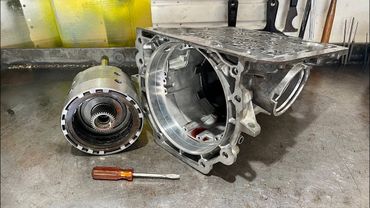
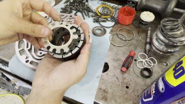
All right, now we're going to go ahead and assemble the reverse input drum.
So fairly straightforward deal.
You're going to have your steels.
These are the tubular steels.
Late model 4L60E 97 and up along with high energy frictions.
And you're also going to have a cushion plate and of course a vacuum plate.
So the 4L60E large square hole drum
And when we say large square hole, this is what we're referring to.
This is going to be your feed port for your applied piston.
This is the drum that is to be installed in all 700R4s.
And that's regardless of the condition of your pre-existing drum.
The reason for that is this drum is the most updated, modernized design available and provides the most fluid volume to this clutch.
the original drums that took the steel pistons those pistons and those drums are dimensionally different than these so in other words you cannot take this piston and try to stick it in a first design drum now those drums are produced between 1982 and i believe uh 1986 or 1987. i can't remember exactly uh which year they
you know, they kind of went out and were replaced by what we call the round hole drums.
The round hole drums are a second design drum and they were in production from 1987 to 1992.
In 1993, this drum, the latest design or third design drum, was introduced and it has since superseded the two previous designs insofar as what needs to be installed into this
into this transmission.
So that applies to all 700R4s and 4L60Es.
So the issue with the first design drum is that it's just not, you know, there's not really a problem with the piston.
I've never heard him, you know, cracking or breaking or whatever, wearing out.
But...
The drums themselves were problematic.
When I recall, they had issues with the piston bleeder orifice.
I'm sorry, the drum bleeder orifice.
The orifice was in the drum, not the piston.
They would sometimes get clogged.
And incidentally, as well, if you're working with those drums, the frictions for 82 to 86 700 R4s in the reverse input clutch were thicker than subsequent years, as well as all years for L60E.
In 96, they changed...
the friction material.
BorgWarner went to a different kind of clutch, a different design, and so that can be retroed back to any year 700 R4.
Transgo makes these little orifice plugs for the bleeder ports in these pistons, so right here.
I'll be honest, I never use them.
I don't believe them to be necessary.
This clutch is only on when you're in reverse.
So the last thing you need is having that little capsule get grit in it and allow fluid to pool in behind the piston and cause it to drag or, you know, drag the clutch or centrifugally apply the clutch causing a massive problem.
Alright, let me go ahead and install my snap ring at the press and then we'll be back and we'll fit this clutch in there and then we'll move on.
All right, cushion plate.
And then it's just steel friction, steel friction.
And then your backing plate and then your snap ring.
So 40 to 70 thousandths clearance is what you want.
If you're under 40 thou, you're gonna wanna swap out the backing plate.
These are selective.
And all years will fit all three designed drums.
So you just gotta find one that works.
4L60Es, I basically never have a problem.
700R4s, occasionally I'll have issues.
We'll see reports of folks, other builders online also discussing problems they're having with excessively tight drums, et cetera.
I mean, I can tell I've been doing this for so long that this is perfectly fine.
Okay, if it was about half this, then you'd want to measure it, but that feels like it's about 55 to 65 thousandths.
That would be my guess.
To air check this drum, all you're really going to do is take a rubber-tipped nozzle and do the best you can to jam it into that square feed port and then apply air to the clutch.
It's actually easier to get it from the backside.
All right.
When you're doing that, make sure that you cannot move the frictions like this.
If you're putting air in there and you can move the frictions all around, then you cut one of the two lip seals or both of them.
All right.
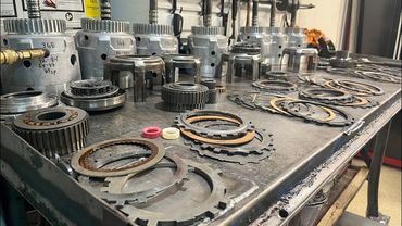
I'm going to drag over some parts for the case.
Starting with the low reverse clutch pack.
Alright, so here we have our center support.
I have a dimension written on the support.
This is the dimension from here up to here.
Okay, that's 265 thousandths.
also have a dimension here on the piston take note of the casting number it ends in 888 and i have a dimension of 2.845 that is this dimension from here to here and then we have our clutch pack in the clutch pack we have a selective if you recall from
The teardown video, I noticed this.
704s and 406Es come with occasionally selective steels in the low reverse clutch pack.
And these steels must be kept.
Do not throw them out.
This is 95 thousandths thick, but the writing wore off, so I'll just show you.
95 thousandths.
So, I have a video that dives deep into the low reverse clutch, and I'll walk you through all the details, but I will summarize them here just so you know.
Basically, what you need to do is measure your clutch pack clearance indirectly.
And so, you're going to have your cushion plate here for all 87 and up, or 80, 80, up 700 R4s.
One of those two years, that's when...
they changed the piston i believe it's 1987 and they went with a cushion plate the piston got shorter to accommodate the addition of the cushion plate all right then you will have your selective steel now many transmissions 700 rs4 l60s will not have a selective steel right there uh all of the steels will be of the 70 thou thick variety
And they'll be unmarked.
This one had one.
So you'll have your steel and then all the rest of your steels and clutches.
And then what you want to do is you want to stack this all up on the bench just like this.
And you want to measure the overall height of the clutch including to the center support.
So right here on the top ledge of the center support.
And what you're looking for is a height of between 1.2 and 1.240.
As long as you're somewhere within that range, you're fine.
So that tells me that this low reverse clutch in its entirety, along with this piston, is good to go.
The piston is matched with the support, and the selective steel there is necessary.
If we didn't have that steel, we'd be 20 thou off.
Now, how consequential is that?
I mean, I don't know, to be perfectly honest.
The other thing I always like to do with all my one-way assemblies
is I will draw an arrow.
These rotate clockwise and lock counterclockwise.
Me drawing the arrow tells me that I have confirmed that the one-way clutch is installed correctly and it's rotating or freewheeling in the right direction.
Now we're going to go ahead and install everything into the case.
Similar videos: The Nemesis
700R4 Rebuild PT1: Overview
4L60E High Performance PT7 - Aftermath
700R4 Rebuild PT4: Pump, Servo, 1-2 Acc and Reverse Input Drum + Solving Rev Input Clearance Problem
2. GM 4L60E Rebuild - Subassemblies
700R4 & 4L60E Forward Drum Changes and Interchange Information 1982-2013