Summary of all Flip-Flops
Download information and video details for Summary of all Flip-Flops
Uploader:
TutorialsPointPublished at:
1/18/2018Views:
549.6KVideo Transcription
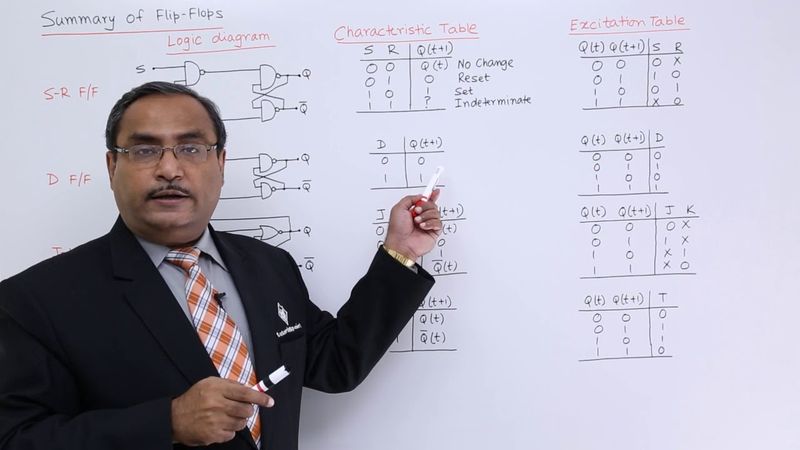
Summary of flip-flops.
In this session, we shall discuss regarding all the flip-flops and how to remember each and every issue.
I shall mention that one explicitly.
so please watch this video very carefully because for any kind of sequential circuit design whether it is a ram circuit design or register or any kind of counters this summary of flip-flops will be required so at first we are going for the sr flip-flop sr stands for set reset flip-flop so this is the circuit for the sr flip-flop we discuss about the details in the respective video always remember
Whenever in the clock logic, we are having NAND, then in the PPLOP logic, we will be having NAND.
Whenever the clock logic is having AND, then the PPLOP logic will be having NOR.
Whenever NAND logic is there, then S will have directly Q.
So, in the same way, if S is there, then Q will be there.
If you mark this one S, then Q should be written here and other one will be Q1, Q bar.
But if you go for AND NOR logic, then S will be having Q bar here and R will be having Q here.
So, remember these issues very carefully.
So, for NAND NAND, S will be facing Q.
For AND NOR, S will be facing Q bar.
This is our characteristic table of
SRV plot.
What is the characteristic table?
We know that when the set is enabled, output will be set, means 1.
When the reset will be enabled, output will be reset, that means 0.
When set and reset, neither one of them is enabled, then there will be no change.
Previous output will be the present output.
And whenever we are having 1, 1, that is indeterminate condition, that is also known as rest condition.
And that is the main problem with our SRV plot.
so now here we are having the respective excitation table so from zero to zero transition we are having zero x why zero x because just think that from zero to zero you can you can think this one in two ways either you are there is no change that there is no change in the output so that means the input should be zero zero and
the output is getting reset for the first for the next time reset then then the input should be input should be 0 1 so just club them merge them 0 0 and 0 1 the input should be 0 x
so zero to one can only be interpreted as the output is getting set so one zero set is enabled one to zero transition can only be interpreted in one way that is output is getting reset so reset will be one set will be zero and one one one means i can think this one in two ways either output is not getting changed so zero zero input output is getting set
So, 1 0 input.
Now, if you want to merge it is x and it is 0.
So, that is why x 0 is there.
Now, I shall go for the D 5th block.
D 5th block is not a new 5th block.
It is simply SR 5th block.
Only S and R are getting connected through one not or inverter.
So, here is the D 5th block where D will be facing Q.
And basic logic of defiplop is that present input will be going to the output after application of the clock pulse.
So the delay is the clock pulse period.
So present input will be the next output after application of the clock pulse.
So that is the basic theme behind defiplop.
So now consider this characteristic table here.
So present input will be the next output.
Present input will be the next output.
So, whatever output you require ultimately that should be the present input and that is the logic of D FIPLOC.
So, again the same if the clock logic is having NAND, the FIPLOC logic will be having NAND, if the clock logic is having AND, the FIPLOC logic will be having NOR.
Now, we are going for this JK FIPLOC.
When the clock logic is having AND, FIPLOC logic will be having NOR, clock logic is having NAND, then FIPLOC logic will be having NAND.
If it is NAND NOR logic, then K will be facing Q and in case of
NAND logic K will be facing Q bar and another change will take place.
That means, Q will be going here and Q bar will be coming here, but the feedback path to K will be going for Q only.
So, the path will be something like this.
So, here this path will be taking from there and this path will be taking from there.
So, there will be a crossover.
So, in this way that is a case for the JKFIP blob using two different circuits.
Now, in case of JK 5th block, it is a 2 bit 5th block because j and k 2 bits are there.
So, 4 input combinations can be possible and it is free from rest condition.
So, here is a respective characteristic table for JK 5th block.
So, for 0 0 it is Q t, for 0 1 it is 0, for 1 0 it is 1 same as the SR 5th block, but for 1 1 it is Q bar t. So, here it was indeterminate, but it is Q bar t.
So, 0 to 0, we can consider in two ways.
That means no change and set.
No change and reset because 0 is there.
No change and reset.
So, input should be 0x as I explained earlier.
0 to 1 can be thought in two different ways.
What is that?
That is set.
Set means input should be 1 0 or output is getting complemented, input should be 1 1.
So, 1 0 and 1 1 if you merge then you are getting 1 and x.
So, you are getting 1 and x there.
From 1 to 0 transition can be thought of in two different ways either the output is getting reset or output is getting complemented.
For reset input should be 0 1, output should be complemented input should be 1 1.
So, if you merge them it is x 1.
So, that is why x 1.
and one one can be thought of in two different ways either it is set or no change so set means this one no change means this one if you merge them it is x0 so that is our jkfee plop
there is a x addition table here.
Next, we are going for the last one that is our T-fiplop.
In case of T-fiplop, the J and K terminal is getting shorted by a simple wave.
So, that is why they are getting directly shorted.
And here is the clock pulse and here is the circuit diagram for the T-fiplop.
And similarly, here if the logic is AND, the fiplop logic will be NOT, if the
logic is NAND, FIPLOC logic will be NAND in that case and here T will be facing Q but at that time T will be facing Q but in this way you can think.
But actually the thing is that also you can consider this one as T, you can consider that one also as T because both are getting shorted.
So, that is our T FIPLOC.
So, T FIPLOC means a special case of JK FIPLOC where T is equal to 0 means
j k is equal to 0 0.
So, that means t 0 means j k 0 0.
So, q t will be the output and t 1 means j k t in case of j k it is 1 1.
So, t 1 means j k is 1 1.
So, that is we are having this q by t here.
So, now if we want to change in the output do you want to change in the output no input should be 0.
Do you require the change in the output?
Yes, input should be 1.
Do you require change in the output?
No, input should be 0.
So, when input is 0, then there is no change in output.
When the input is 1, there is a change in the output and that is the logic of T FIP block.
In case of circuit design, sequential circuit design.
We remember the sequence that is 0 x 1 x x 1 x 0.
If you can remember this one, this particular excitation tables are very simple for d and t. They are very simple, but just remember the respective sequence for the j k excitation table.
So, it is 0 x 1 x x 1 x 0.
If you can remember this one, it is very simple.
It is 0 x
it is not 1 0 it is not 1 x it is 1 0 then it is 0 1 and this is minus x 0.
So, that is why in the exam one question may come that j k flip flop is more flexible than s r flip flop how to answer this one.
You can answer this one in this way that in case of 0 to 1 transition in case of j k flip flop I require to have 1 in j, but anything
is allowed in k, but in case of 0 to 1 transition we require 1 in s and 0 in r. For 1 to 0 transition I require 0 in s and 1 in r, but here anything in j and 1 in k. So, that is another answer to prove that j k flip flop is flexible than s r flip flop.
So, please remember the sequence that is 0 x 1 x x 1 x 0.
Similarly, you can have this one as 0 x 1 0 0 1 and x 0.
So, that is this is the respective excitation table for SFE plot.
Other excitation tables are quite simple.
You can easily get it as when you want to recall it.
Thanks for watching this video.
Similar videos: Summary of all Flip

Flip-Flop - Introduction
BATTLING FOR DOMINANCE Working on the Left Front Leg at an Odd Angle

آموزش دوخت سجاف با نوار اریب | آموزش خیاطی با استاد زرین کفاش

Только эти 4 видео из всех тебе нужно посмотреть обязательно
![RC SCALE I CRAWLERS I SLOW MOTION [Special Video] 2019/2020](https://videodownloadbot.com/images/video/074/nkpey2rknjr6qho3os5czej2v2i5dq1b_medium.jpeg)
RC SCALE I CRAWLERS I SLOW MOTION [Special Video] 2019/2020